Raspberry Pi Pico controlled RGB LED lighting in my Homelab server case
Table of Contents
- Introduction
- Things you're going to need
- Setting up the hardware for development
- MicroPython code to control the LED strip
- Setting up the hardware for use
- Done
Introduction
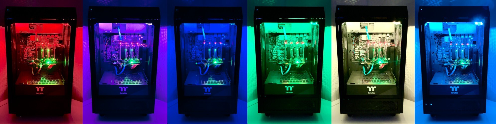
Building on the momentum from my previous adventure in building my homelab AI cloud server, I've decided to inject a hint more colour into my setup. I could opt for off-the-shelf RGB lighting solutions, like an RGB case fan, but where is the fun and learning that?
This post is a walkthrough of how I've added custom RGB LED lighting to my homelab server case, controlled using the versatile Raspberry Pi Pico.
A shout-out to the The Pi Hut's - Maker Advent Calendar, a growing festive tradition that's captivated both my children and me for a couple of years now. As I was plannig the enhancements to my server case, I realised the components from the calendar could be repurposed—giving new life to them beyond our Xmas experiments. I'm using the 2022 calendar - specifically the Pico and LED strip component from Day 12.
Fair warning: As we proceed, remember that the path may not be one-size-fits-all. The steps I share are from my own experiences, filtering out the errors along the way. You might come across other troubles, or even find simpler ways of doing things, but my hope is that by sharing this knowledge, you'll be equipped with the best chance of success. Be prepared to invest time, energy, and a modest amount of cash - after all, the rewards will be worth it. You should be as comfortable with the chance of breaking things and starting over. And, crucially, secure the blessing of your family; you might just disappear into your lab a little longer than expected.
Electrical caution: Just a friendly reminder that I'm sharing my personal escapades in electronics, without formal qualifications in the field. The insights here should not be mistaken for certified electrical instruction. Proceed with caution and at your own discretion; even low-voltage projects can cause problems.
Note: I have received no sponsorships from any companies or people mentioned in this article, although offers would be very welcome 😉. Links to products/services do not constitute recommendations.
Things you're going to need
Before we dive in, remember that these are the components that suited my project. Depending on your setup, you may need to make some adjustments. The following list is what I've used.
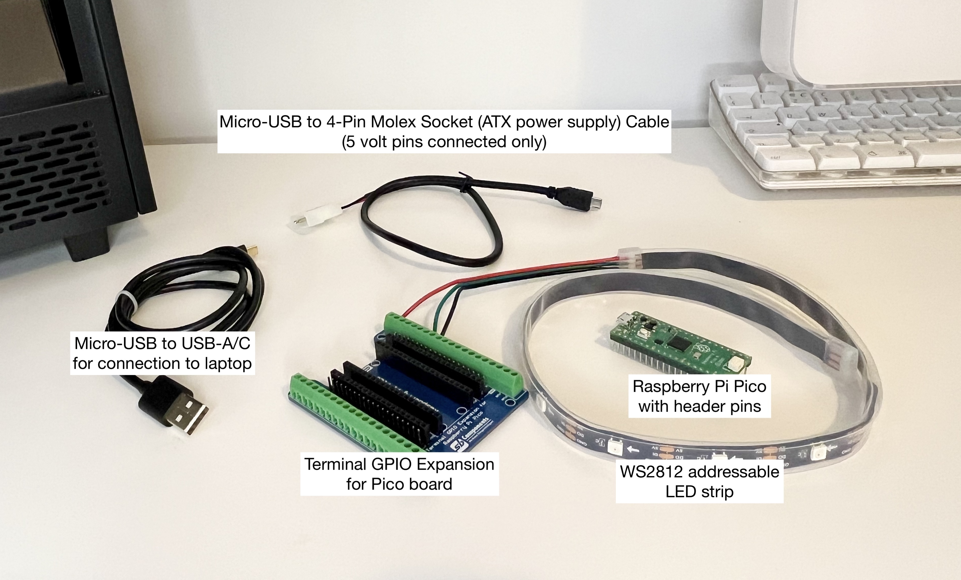
- A computer with a development IDE installed. I've opted for simplicity with Thonny, as suggested by the Raspberry Pi creators. You can read the installation instructions here
- Raspberry Pi Pico with header pins soldered on. If you're not up for a bit of soldering, you can purchase one with pre-soldered headers. For this guide, I'm not using any network capabilities, so the Raspberry Pi Pico H from the Advent Calendar will do. Ensure you've got the MicroPython firmware flashed onto the Pico; here's how
- Terminal GPIO Expansion for the Pico board - I got mine from The Pi Hut
For Development
- A high-quality Micro-USB to USB-A (or USB-C) cable for connecting to your computer, capable of delivering both power and data
For installation into the server case
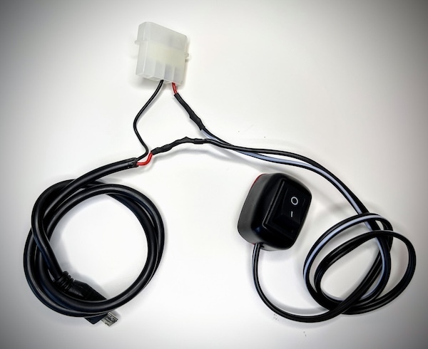
- A 5-volt power supply. I've repurposed a spare connector from my ATX PSU, using a Micro-USB to 4-Pin Molex Socket Cable — only the 5-volt pins are in use. Alternatively, you could power the Pico directly from certain pins, but I'm sticking with the Micro-USB approach for my use-case
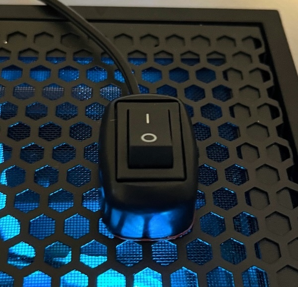
- Optionally, include a power switch to easily toggle power to the Pico and LED strip. If your setup already includes a power-down feature, feel free to skip this part. I've opted for a remote switch like this one, as my server case is always on. If you're handy, you might consider installing a manual switch directly on the case
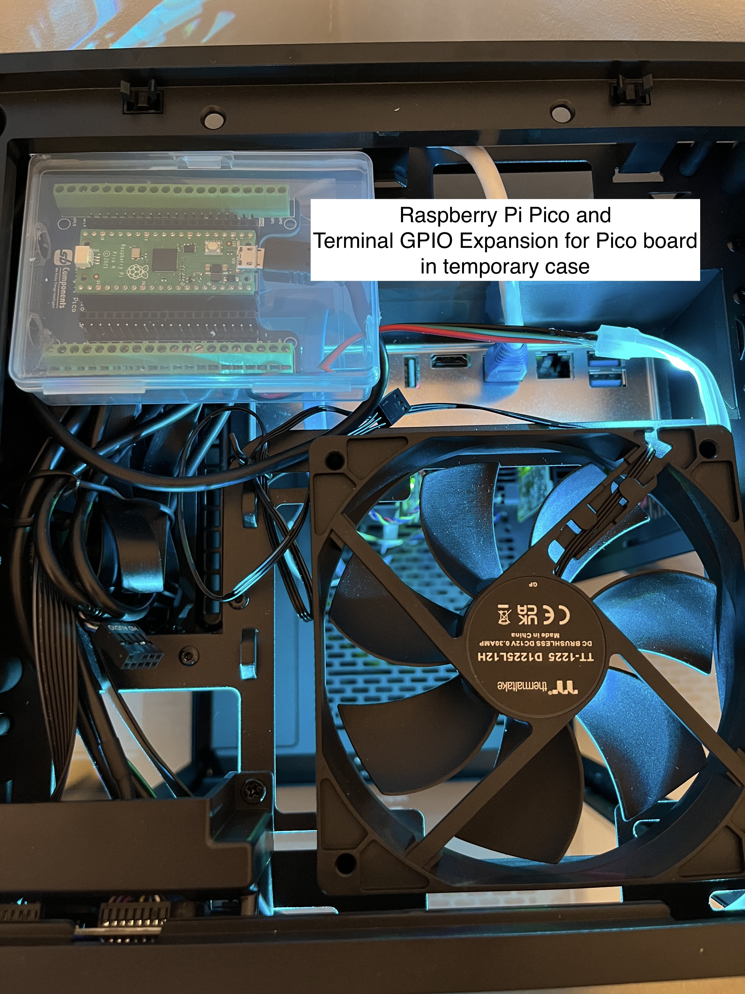
- A protective case for the Pico and Terminal board, or secure mountings to prevent any shorts. I'm currently using a stopgap solution, but I'm planning a custom 3D-printed case for a future upgrade. You'll see my interim setup later in the post
- Appropriate fittings to secure the LED strip in place, ensuring it's both aesthetically pleasing and functional
Note: The LED strip I used contains 15 LEDs and is about 0.5 metre in length. Ensure that your power supply can handle the current draw of your specific LED configuration.
Setting up the Hardware for Development
Follow these steps to get the hardware ready for development:
- Carefully insert the Raspberry Pi Pico (with headers) into the Terminal GPIO Expansion board, ensuring it's oriented correctly
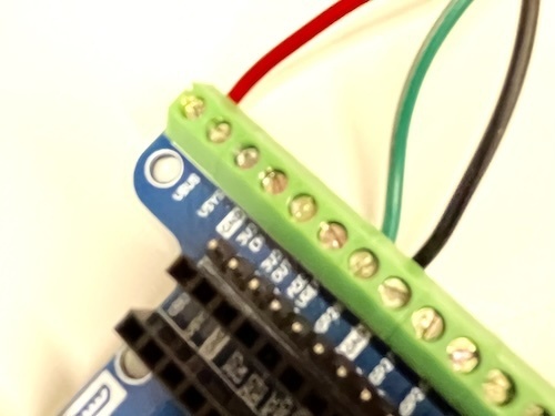
- Connect the LED strip's data input to the designated GPIO pin on the expansion board – in my case, I'm using GPIO pin 28
- Attach the LED strip's positive power wire to the VBUS terminal on the expansion board
- Secure the LED strip's negative ground wire to one of the ground terminals on the expansion board
- Finally, connect the Pico to your laptop using a micro-USB cable to provide power and enable data transfer
Notes:
- As with any electrical project, ensure the power is off before making connections to prevent any damage or injury
- Make sure to connect the correct wires to the correct terminals from the LED strip, as connecting it backward could damage the strip or the Pico
- Insulate any exposed connections using electrical tape or heat-shrink tubing for added safety
MicroPython code to control the LED strip
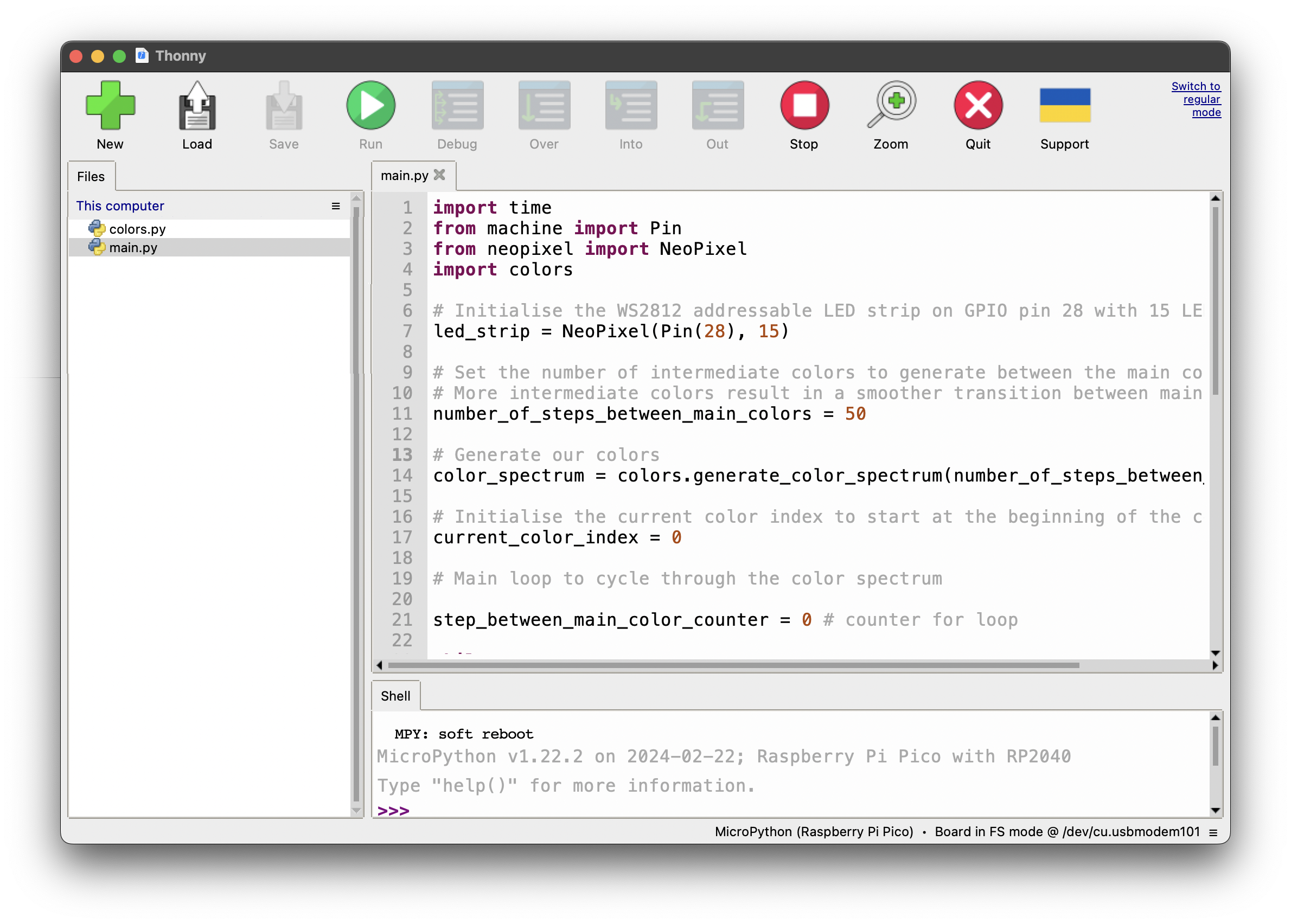
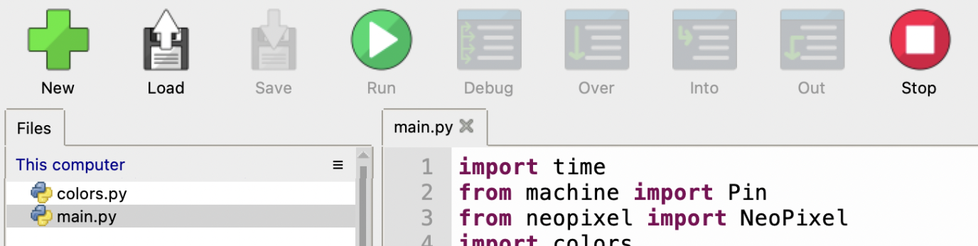
To program the Raspberry Pi Pico, we'll use the Thonny IDE. Our goal is to create two separate Python files for better code organisation and potential reuse in future projects.
Firstly, create a file called colors.py. This module will house functions responsible for generating color patterns and handling color transitions. Keeping these functions separate from our main script keeps our codebase tidy and modular.
# colors.pydef generate_color_spectrum(number_of_steps_between_main_colors):    """    Generates a spectrum of colors by interpolating between main colors.
    The function creates a smooth gradient by calculating intermediate colors    between the main colors. The number of steps between each main color    determines the smoothness of the gradient.
    :param number_of_steps_between_main_colors: The number of intermediate colors to generate between main colors    :return: A list of RGB color tuples representing the color spectrum    """
    def interpolate(start, end, step, number_of_steps_between_main_colors):        """        Interpolates between two RGB colors for a given step calculate        the intermediate color at a specific step between the start and        end colors.
        :param start: A tuple representing the start color (RGB)        :param end: A tuple representing the end color (RGB)        :param step: The current step number in the interpolation process        :param number_of_steps_between_main_colors: The total number of steps for interpolation        :return: A tuple representing the interpolated RGB color        """        return [(int(start[i] + (float(end[i] - start[i]) / number_of_steps_between_main_colors) * step)) for i in range(3)]
    # Define the main colors to create the gradient between    main_colors = [(255, 0, 0), (255, 255, 0), (0, 255, 0), (0, 255, 255), (0, 0, 255), (255, 0, 255), (255, 0, 0)]
    # Generate the color spectrum by interpolating between each pair of main colors    colors = []    for i in range(len(main_colors) - 1):        for step in range(number_of_steps_between_main_colors):            colors.append(interpolate(main_colors[i], main_colors[i + 1], step, number_of_steps_between_main_colors))
    return colors
def next_color_index(current_color_index, total_colors):    """    Computes the index of the next color in the spectrum.
    This function ensures the color index cycles through the spectrum, resetting    to zero when it reaches the end of the list.
    :param current_color_index: The index of the current color in the spectrum    :param total_colors: The total number of colors in the spectrum    :return: The index of the next color in the spectrum    """    return 0 if current_color_index == (total_colors - 1) else current_color_index + 1
Next, we create the main.py file. The Raspberry Pi Pico looks for a file with this name to execute on boot (after boot.py - but we don't need this file for this project). Our main.py will contain the primary logic that drives the LED strip's behavior.
In this example we cycle through a smooth gradient of colors. In future, we could add different effects.
# main.pyimport timefrom machine import Pinfrom neopixel import NeoPixelimport colors
# Initialise the WS2812 addressable LED strip on GPIO pin 28 with 15 LEDsled_strip = NeoPixel(Pin(28), 15)
# Set the number of intermediate colors to generate between the main colors# More intermediate colors result in a smoother transition between main colorsnumber_of_steps_between_main_colors = 50
# Generate our colorscolor_spectrum = colors.generate_color_spectrum(number_of_steps_between_main_colors)
# Initialise the current color index to start at the beginning of the color spectrumcurrent_color_index = 0
# Main loop to cycle through the color spectrum
step_between_main_color_counter = 0 # counter for loop
while True:    # Determine the next color index and retrieve the corresponding color from the spectrum    next_color_index = colors.next_color_index(current_color_index, len(color_spectrum))    next_color = color_spectrum[next_color_index]        # Apply the next color to the entire LED strip    led_strip.fill(next_color)    led_strip.write()        # Update the current color index to the next color index for the following iteration    current_color_index = next_color_index        # Introduce a short delay to allow the human eye to perceive the color transition    # A delay that is too long will result in noticeable jumps between colors    time.sleep(0.04)        # Increment a counter that tracks the number of intermediate colors displayed since the last main color    step_between_main_color_counter += 1        # Check if the next main color has been reached in the spectrum    if step_between_main_color_counter == number_of_steps_between_main_colors:        # Output the current main color to the console        print(f"Color: {color_spectrum[current_color_index]}")                # Pause on the current main color for a longer duration to emphasixe it        time.sleep(10)                # Reset the counter to begin transitioning from the current main color to the next one.        step_between_main_color_counter = 0
Before uploading the code to the Pico, you can give it a try directly in Thonny by clicking the 'Run' button. If you make any edits while the code is running, remember to press 'Stop' before hitting 'Run' again to see the changes in action.
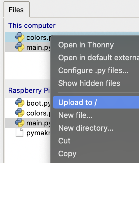
Once you're satisfied with the code and LED light effects, it's time to transfer the code onto the Pico. Simply use Thonny's file upload feature to move both colors.py and main.py onto the Pico.
Remember to save files regularly as you make changes, and keep backups in case you need to revert to a previous version.
Setting up the hardware for use
Integrating a power switch into the setup provides a convenient way to power the Pico and LED strip system on and off. If you opt for a power switch, integrate it by soldering it in-line with the positive power cable. I chose a remote switch for ease of use, securing the connections with solder and heat shrink tubing for a [semi] professional finish
Once the switch is in place, connect the 4-Pin Molex Socket to an available connector on the ATX power supply. Then, plug the micro-USB end into the Pico to provide it with power. Alternatively use the power source of your choice.
Next, I put the Pico and terminal board in a temporary case and mounted it in the top section of my server case. While this setup is provisional, I'm exploring the design of a custom 3D-printed case for a more permanent and aesthetically pleasing solution. Bear with me and my work-in-progress enclosure as illustrated below.
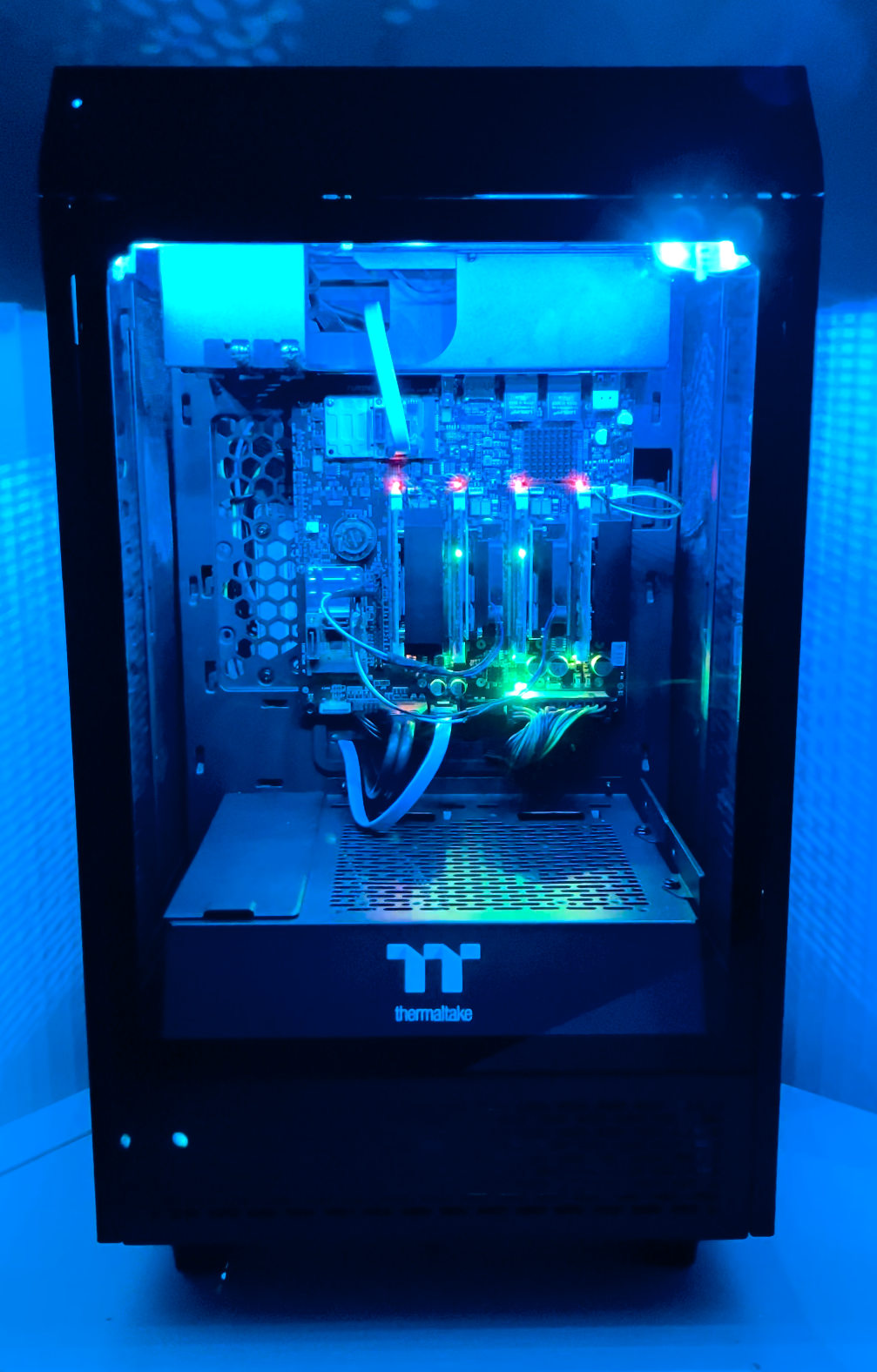
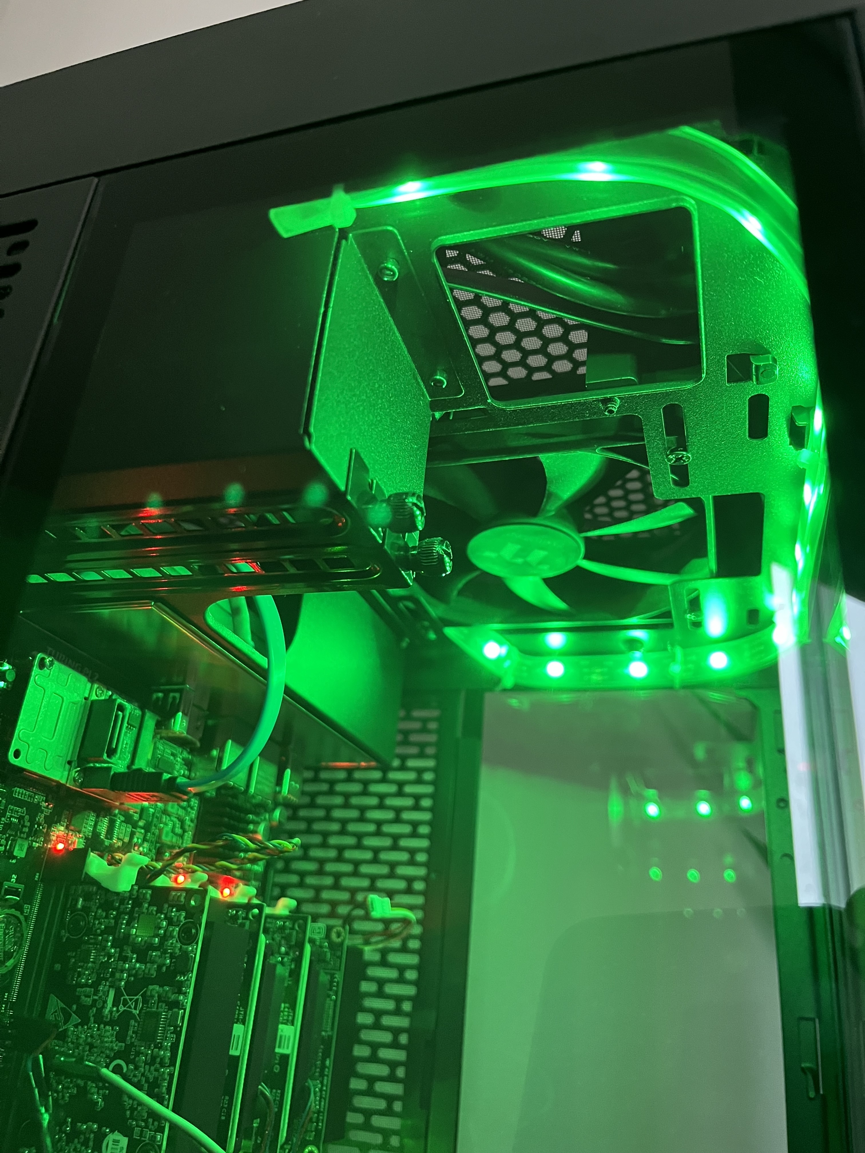
Finally, I fitted the LED strip within the main compartment of the server case, taking care to secure it in place. With everything connected and mounted, I switched it on and now have some vibrant LED lighting to compliment the setup.
Done
Looking ahead, I'm keen to further experiement with the capabilities of the Raspberry Pi Pico and the Terminal GPIO Expansion board. I want to try a setup where the case fans speed is dynamically controlled by a PWM (Pulse Width Modulation) module, responding to real-time temperature readings from a sensor.
Stay tuned for future posts where I'll delve into these upgrades and provide a walkthrough so you can replicate or adapt these ideas for your own setups.